Permittivity (Dielectric Constant) and Loss Tangent (Dissipation Factor) of Materials (Two Fluid Cell Method)
1.0 Scope
1.1 Purpose This method is suitable for determining the volume permittivity, (dielectric constant) and loss tangent (dissipation factor) of insulating materials at 1 MHz. It is not dependent on either direct or indirect measurement of specimen thickness and therefore is very useful for thin films and laminates but may also be used on specimens up to approximately 6.35 mm [0.25 in] thick. It is useful for all ranges of permittivity and for loss tangent as low as 0.0005 providing the range and accuracy of the bridge used are adequate.
1.2 Description of Method The two fluid method utilizes air as one fluid and a suitable liquid, normally Dow 200 1.0CS silicone fluid, as the second. Using an established value for the permittivity of air, the values for the permittivity of the fluid and the sample may easily be calculated. The cell spacing is fixed during all readings but does not need to be known accurately for the series of readings required. Since specimens do not require any electrodes to be applied and since many specimens can be measured at one time without changing any spacings or machine settings, the method is not only very accurate but very rapid. The method has been used for measurement of PTFE and epoxy glass laminates and flexible films, e.g., polyimide. Reproducibility lab to lab is excellent for permittivity provided minimal precautions are observed and bridge accuracy is appropriate. On most materials, the effects of small changes in moisture or temperature are larger than any error due to the method. Lab to lab correlation on stable material such as PTFE have shown results to be consistently within 0.005 or (0.20%).
2.0 Applicable Document
3.0 Test Specimens
3.1 Number Unless otherwise specified in the material specification, one specimen is adequate for materials which are uniform, e.g., unreinforced plastics. For woven reinforced materials where resin content may vary, at least 2 specimens, representing the thinnest and thickest part of the sample, should be tested. For material with random reinforcement, a minimum of three specimens from the edge and center of the sheet are recommended to characterize variation within the sheet.
3.2 Form Individual specimens shall be 81.3 mm ± 1.3 mm x 81.3 to 101.6 mm [3.2 in ± 0.05 in x 3.2 in to 4.0 in] x thickness. For materials under 0.254 mm [0.010 in], individual specimens should be stacked to a minimum of 0.381 mm [0.015 in] to maximize accuracy. Thinner specimen buildups may be used if the correlation with the 0.381 mm [0.015 in] specimen is within the required accuracy for the particular equipment, cell spacing and material being tested.
3.3 Foil Clad Materials All foil clad materials shall have the metal cladding completely removed by etching and shall be rinsed and dried prior to conditioning.
3.4 Marking Mark each specimen in the upper left corner with an engraving pencil or an ink which is not soluble in the Dow Corning 200 fluid.
4.0 Apparatus/Materials
4.1 1 MHz Capacitance Bridge with 0-200 (or 0-100) pf range.1
4.2 Cell Balsbaugh LD-32 or equivalent (see Figure 1) three terminal cell. Note: For accuracy of 1% or better, room temꢀperature must not vary more than 1°C during measurements. Temperature control is necessary if laboratory variation exceeds these limits
4.3 Test Leads 2 RG 58/U coax cables approximately 304.8 mm [12 in] long with suitable connectors for the bridge. One lead shall have a banana plug (high lead) and the low lead should have a GR8743 at the cell end. (Note: The use of a G874-QBJA4 instead of the standard GR874 will permit a BNC5 connector to be used for the cell connection of the low lead, reducing the chances of damaging the 874 connector.)
4.4 Flask with stopper (for silicone fluid storage).
4.5 Beaker for cell overflow.
4.6 Funnel.
4.7 Filter paper (coarse).
4.8 1 Centistoke Dow Corning 200 Fluid (500 ml minimum).
Note: Fluid must be at the same ambient temperature as the test cell and should be stored in close proximity to the test cell.
4.9 Forceps or large tweezers.
5.0 Procedure
5.1 Conditioning All materials which are affected by moisture, including all reinforced laminates and most films, should be conditioned at 23°C ± 2°C 50 ± 5% RH for a minimum of 24 hours prior to testing. If required by the specification, specimens may be tested after humidity or water immersion or tested after desiccation.
5.2 Test Conditions For ambient temperature tests the temperature should be 23°C ± 2°C. Note: Variation should not exceed 1°C during the test. Ambient humidity is not critical for most materials. The exception is very thin, very hydroscopic material such as polyimide film, where moisture content may be well over 1%. Such material must be tested at the desired humidity since the dielectric constant will increase measurably with moisture content and changes may occur very rapidly after removal from a controlled environment. For materials which experience glass transitions in the room temperature region, e.g., PTFE, some acrylics, the temperature should be 23°C ± 1°C.
5.3 Set Up
5.3.1 Open the electrode on the cell. Blow out the cell using clean compressed air to remove any dust or silicone fluid.
5.3.2 Warm up the bridge for at least the minimum amount of time recommended by the manufacturer.
5.3.3 Attach the low lead to the guarded electrode of the cell and the bridge.
5.3.4 Attach the high lead to the bridge and place the banana plug in the vicinity of, but not touching, the banana plug jack of the test cell.
Note: Be certain the shielding on the high lead does not conꢀtact the banana plug.
5.3.5 Set the bridge up on appropriate ranges: Capacitance: 200 pf (or 100 pf) Conductance: microsiemens 0-2 PTFE and very low loss material. 0-20 Epoxy and other moderate loss materials. 0-200 Some phenolic and very high loss materials.
Note: For very thick specimens >3.18 mm [>0.125 in] the 0 to 20 pf range can often be used, increasing the precision of the measurement. All values must be obtained on
the same range for both capacitance and conductance.
5.3.6 Set the cell spacing on the LD-3 to approximately 125% of the material thickness 0.51 mm minimum to 7.62 [0.020 in minimum to 0.3 in] Note: The spacing may be as little as 10% or as much as 50% greater than specimen thickness without a significant effect on results.
5.3.7 Zero the bridge for both capacitance and conductance.
5.4 Measurement
5.4.1 Connect the banana plug of the high lead to the cell.
5.4.2 Record the capacitance of the air filled cell as C1 to the nearest .01 pf (or nearest .001 pf if the 0-20 pf scale is used).
5.4.3 Remove the specimen from the humidity controlled environment.
5.4.4 Insert the first specimen to be tested with the marked corner remaining in the upper left and the right side of the test specimen against one side of the test cell.
Note:This will ensure that subsequent measurements are taken using the same area of the specimen.
5.4.5 Read and record the value of capacitance with the specimen in the cell as C3.
5.4.6 Remove the first specimen and obtain C3 for any other specimens to be measured with same cell spacing.
5.4.7 After removing the last specimen from the cell, fill the cell with Dow Corning 200 Fluid using the funnel and a filter to remove any small particles from the fluid and collect any excess fluid from the overflow pipe on the cell with the small beaker.
5.4.8 Allow a few seconds for the temperature of the cell and fluid to equilibrate and record the capacitance of the liquid filled cell as C2. Note: If the capacitance is drifting consistently in one direction, the fluid is not at equilibrium.
5.4.9 Record the conductance of the fluid filled as cell G1. Note: The value obtained will vary somewhat with cell spacing and humidity but should not exceed 500 microsiemen (200 microsiemen if low loss material, with a loss tangent under .001 is being tested). Values beyond this are generally indicative of problems with the leads, contamination of the fluid or bridge error and must be corrected if correct dissipation factor is to be determined.
5.4.10 Insert the first specimen in the fluid filled cell exactly as in the dry reading and record the value of the capacitance as C4 and the value of the conductance as G2.
Note: Values should stabilize within a few seconds after specimen insertion. If they do not there is very likely air trapped in the cell. This is quite common if multiple thin specimens are used to form one test specimen. If this occurs presoaking the specimen with fluid before immersion and inserting one ply at a time should eliminate the problem.
5.4.11 Remove the first specimen and insert each subseꢀquent specimen in the same order as the dry values were obtained and record the C4 and G2 values for each.
5.4.12 After the last specimen is measured and removed from fluid, check and record the values of the capacitance and conductance.
Note: If the level of the fluid with the specimen removed does not cover the electrodes, fill the cell before checking the final values. This check on C2 will be used to verify the amount of influence that changes in ambient temperature have had on the values obtained.
6.0 Calculation
6.1 Calculate the value of the permittivity (dielectric constant) of each specimen tested using the equation:
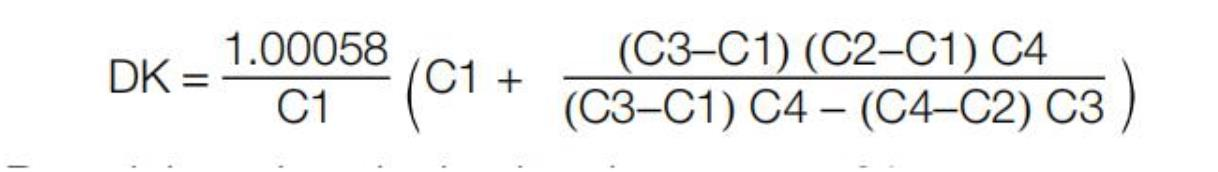
Round the value obtained to the nearest .01.
6.2 Calculate the value of the loss tangent (dissipation factor) of each specimen tested using the equation:
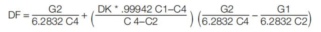
Round the value to the nearest .0001.
Note: Values should be calculated using a computer and must not be rounded prematurely.
6.3 If the value of C2 changed during the course of the measurements, use the final values of C2 and G2, the value of C1, and the values on the last specimen for C3 and C4 to recalcuꢀlate the DK and Df of the final specimen. If the difference in DK values is significant, the temperature of the cell must be conꢀtrolled more precisely during the measurement period.
6.4 Calculate the average permittivity (dielectric constant) (if more than one specimen was tested).
6.5 Calculate the average loss tangent (dissipation factor) (if more than one specimen was tested).
7.0 Report
7.1 Report the minimum, maximum and average values of the permittivity (dielectric constant).
7.2 Report the average value of the loss tangent (dissipation factor).
7.3 Report the specimen preconditioning, e.g., C-24/23/50.
7.4 Report the actual test conditions for temperature and humidity.
7.5 Report if the specimen was built up. 7.6 Report the approximate cell spacing.
7.7 Report any anomalies in the test or variations from the prescribed procedures or tolerances.