Dielectric Constant and Dissipation Factor of Printed Wiring Board Material—Clip Method
1.0 Scope This test method is to determine the dielectric constant and dissipation factor of raw printed wiring board material at 1 MHz.
2.0 Applicable Documents None
3.0 Test Specimens Each specimen shall be 50.8 ± 0.076 mm [2.0 ± 0.003 in] in diameter by thickness of laminate or substrate material. Remove copper of metal-clad specimens by etching using standard commercial practices. At least three specimens are required.
4.0 Equipment/Apparatus
4.1 Meter A 1 MHz Digital LCR Meter, Hewlett Packard Mdl 4271A or equivalent.
4.2 Test Fixture Hewlett Packard Mdl 16022A test fixture or equivalent.
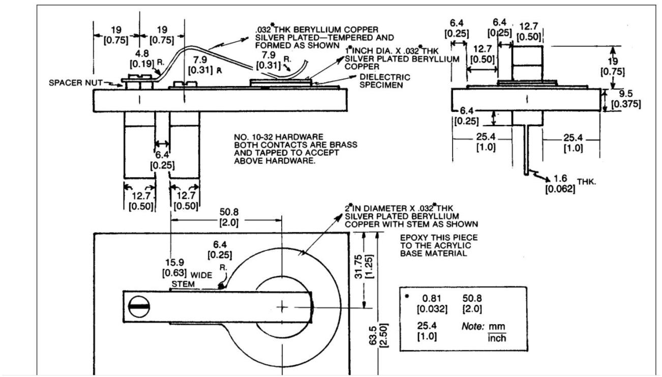
4.3 Specimen Holder A special specimen holder made as shown in Figure 1. This holder is designed to be compatible with the H/P test fixture, Mdl 16022A.
4.0 Procedure
5.1 Preparation
5.1.1 Prepare the specimens as specified in paragraph 3.0.
5.1.2 Calculate the effect thickness (inches) = Mass = Measured weight in grams Density = Grams per cubic cm (as per ASTM-D-792, Method 1A)

5.1.3 Coat both sides of specimens with one uniform coating of silver conductive paint.
5.1.4 Air-dry the specimens until dry to touch, then oven-dry at 50° ± 2°C for 1/2 hour and cool in a desiccator.
5.1.5 Punch or machine a 25.4 mm [1.0 in] diameter disc from the 50.8 mm [2.0 in] specimens. (Assure that there is no carry over of the paint from one side to the other.)
5.1.6 Condition the 25.4 mm [1.0 in] specimens for a minimum of 40 hours at 23° ± 5°C at a relative humidity of 50%.
5.2 Testing
5.2.1 Turn meter on and allow to warm up for 60 minutes minimum.
5.2.1.1 Set the controls on the meter as follows: Function – C-D Range – Manual Trigger – Internal Rate – FCW Test Signal Level – Low
5.2.1.2 Connect the cables for the test fixture to the appropriate connectors. 5.2.2 Plug the special specimen holder into the test fixture.
5.2.3 The digital display on the meter will show the capacitance value and the dissipation factor of the unknown dielectric specimen.
5.3 Calculation
5.3.1 Dielectric Constant The dielectric constant shall be determined by using the following formula:
K = Ct 0.225 A
K = Dielectric constant
C = Capacitance reading from Mdl 4271A Meter
A = Area of a 1-inch disc (square inches)
t = Effective thickness (inches)
5.3.2 Dissipation Factor The dissipation factor value is read directly from the digital display.
5.4 Report The report shall contain the following:
1. Measurement of effective thickness of specimens tested.
2. Capacitance values of the specimens tested.
3. Calculated dielectric constants and averaged measurement.
4. Dissipation factor values and averaged measurement.
6.0 Notes
6.1 The dielectric constant is defined as the ratio of the capacitance with the test material between the two plates to the capacitance of air between two plates.
6.2 The dissipation factor of a dielectric material is the relationship between the permittivity (capacitance of material) and conductivity (ability to conduct or the reciprocal of the electrical resistivity) measured at a given frequency.