Conductor Temperature Rise Due to Current Changes in Conductors
1.0 Scope This method is to comparatively determine the effects of printed conductor materials, conductor cross sectional measurements, substrate materials, and processes on the temperature D.C. current characteristics of printed wiring boards on a standard test sample. The temperature rise must be given for each conductor mateꢀ rials for a particular value of current, for a specified conductor cross sectional area, approximate geometry and substrate material. The results are reported as a plot of temperature rises versus current for each of the conductor materials, cross sectional areas, approximate geometry, and a substrate material.
2.0 Applicable Documents ASTM B 193 Conductor Materials, Electrical, Resistivity of QQ-S-571 Solder, Tin Alloy, Tin-lead Alloy, and Lead Alloy
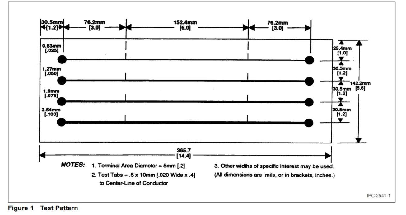
3.0 Test Specimens Standard test specimen, see Figure 1 Test Pattern. Only one test pattern may be tested at one time, with current passing through only one conductor at one time.
4.0 Apparatus
4.1 Potentiometer (0.02% or better accuracy), Leeds and Northrup type K3 or equivalent.
4.2 Resistors (0.1 ohm ± 0.01 ohm) (Caution: Do not use low voltage because of fluctuation.)
4.3 Current leads, #12 AWG stranded wire.
4.4 Potential leads, #26 AWG magnet wire.
4.5 Sn60, Sn62, or Sn63 solder per Federal Specification QQ-S-571.
4.6 Temperature chamber capable of maintaining required temperatures in specification.
4.7 Thermometer or other temperature measuring device suitable for measuring laboratory ambient to the nearest 0.5°C [0.9°F].
4.8 Apparatus for performing cross sections.
4.9 A power supply with range of at least 0-40 volts.
4.10 Digital Multimeter capable of taking current and voltage in specification.
5.0 Test
5.1 Preparation
5.1.1 Extraneous surface coating shall be removed without affecting the dimensions of the conductor. The sample shall represent the materials and processes under investigation.
5.1.2 Current leads shall be secured by soldering to the terminal area. Pretinning of parts prior to soldering is advisable.
5.1.3 Potential leads shall be secured to the test tabs by soldering. Pretinning of parts prior to soldering is advisable.
5.1.4 The ambient air temperature measured at approximately 101.6 mm [4″] perpendicularly from the center of the conductor side of the board shall be 25° ± 5°C [77° ± 9°F]. The temperature shall be recorded at each measurement.
5.2 Procedure
5.2.1 The test sample shown in Figure 1 shall be suspended by the four corners, and centrally located within an enclosure free of forced air movement. The sample shall be so oriented that the conductors are horizontal.
5.2.2 To achieve 3-figure significance in temperature rise measurements, all potentials should be measured accurately to four significant figures.
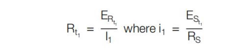
5.2.3 The resistance of the conductor at the reference temperature (Rt1 ) should be determined with a test current not to exceed 100 milliamperes applied for as short a time as possible. (Caution: Do not use low voltage because of fluctuation.)
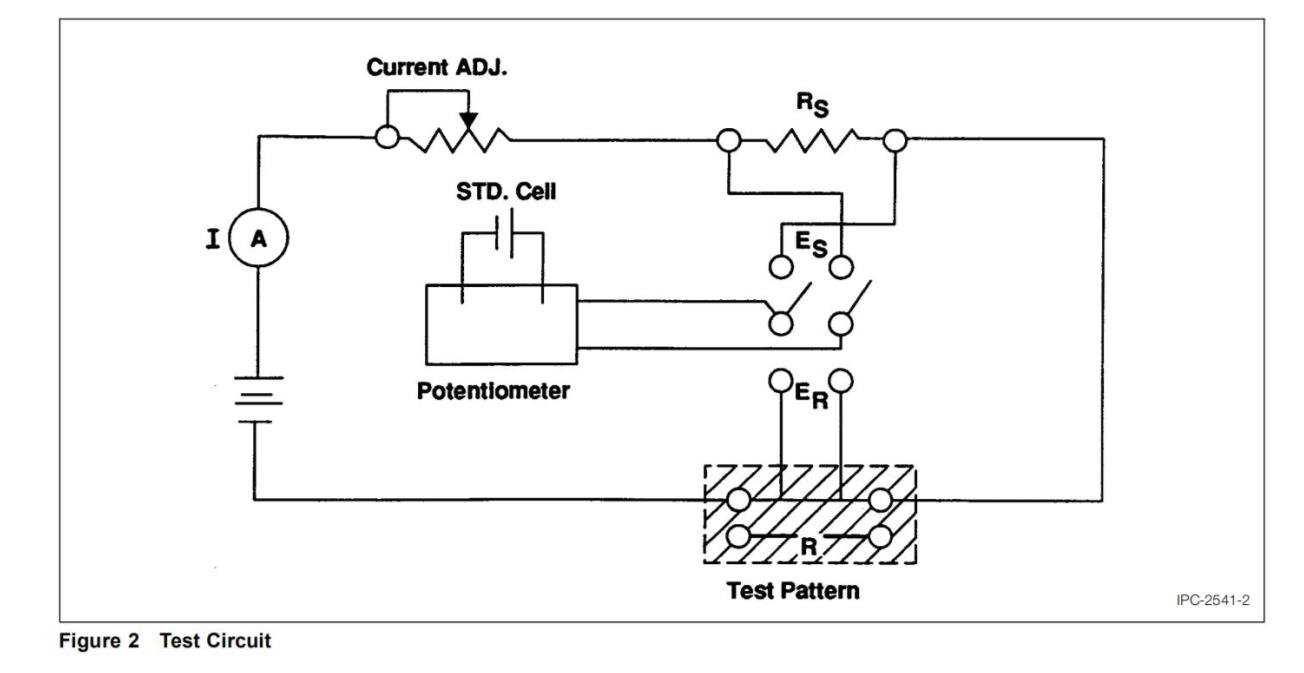
5.2.4 Pass the conductor current through an external series resistor (Rs) having a maximum temperature coefficient of resistance of 0.00002 per degree C at 25°C. The function of this resistor is to provide a reference for measuring the current. Its value should be of the same order of magnitude as that of the conductor under test tminimize scale changes in measurements.
5.2.5 Measurements at specific currents are to be made after thermal stabilization. The elapsed time between these two measurements should be as small as possible.
5.2.6 Measure the voltage drops across the external series resistor and the test section of the current carrying conductor (R).
5.3 Evaluation
5.3.1 The value of the temperature coefficient of resistance (α) shall have been determined and identified. Temperature coefficients for various electrical conductor materials are given in American Society for Testing Materials-B193-65.
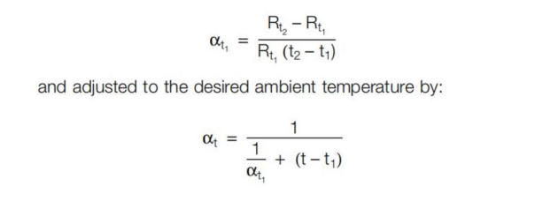
5.3.2 When the temperature coefficient of resistance of the conductor is unknown, it may be determined by measuring the resistance of the conductor at different oven temperatures, and calculated by the formula:
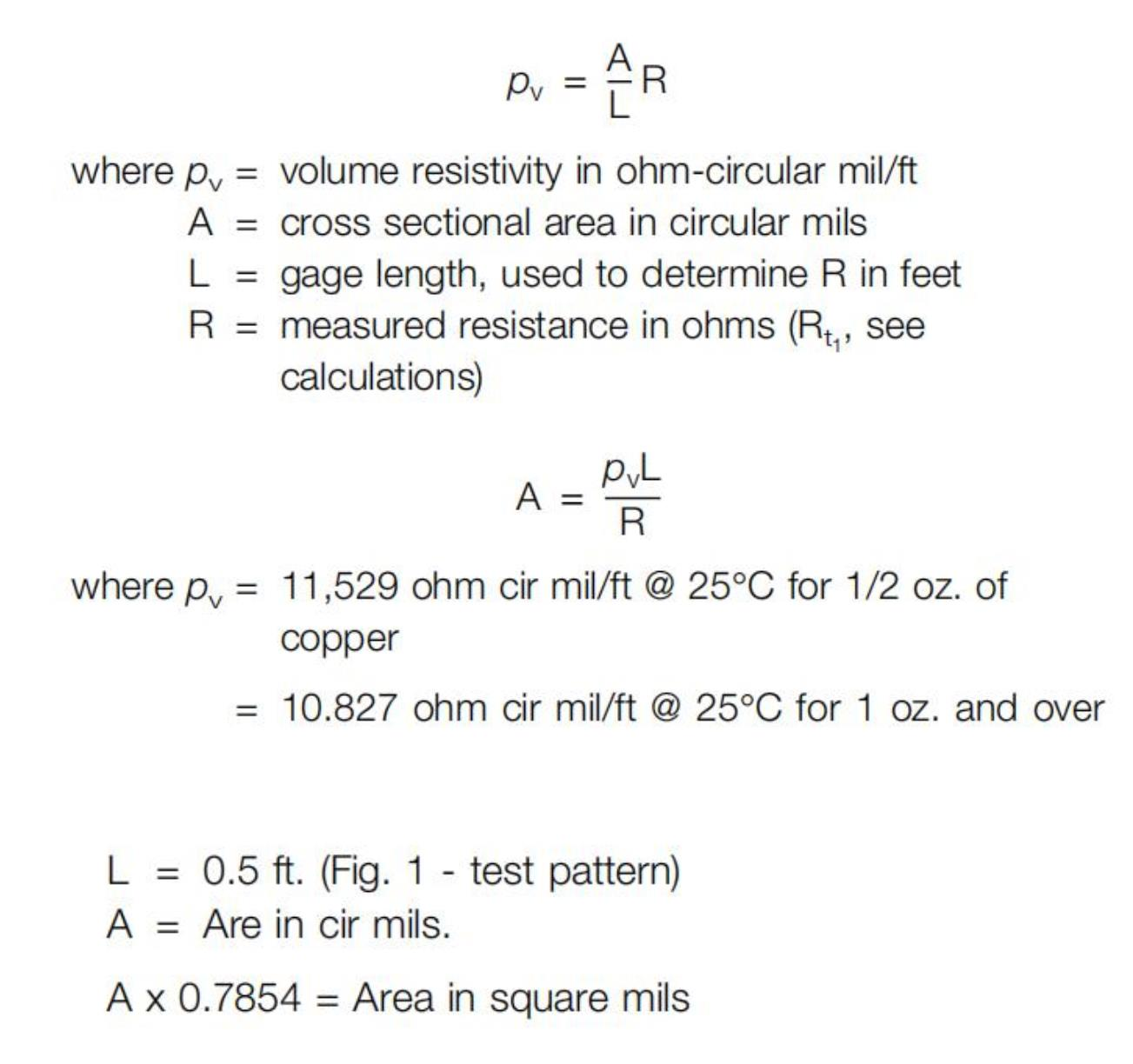
5.3.3 Determine the cross sectional area of the conductor under test by use of the formula for volume resistivity
5.4 Calculations The temperature rise of a conductor is determined by measuring the change in resistance of the test length of conductor and using the relationship.

Rt = Resistance of conductor at the desired current.
Rt = Resistance of conductor at reference temperature (t1).
αt1 = Temperature coefficient of resistance of conductor at reference temperature (t1).
t1 = Reference temperature; that ambient temperature at which Rt1 was measured.
The following relationship can be derived from the foregoing using voltage drops:
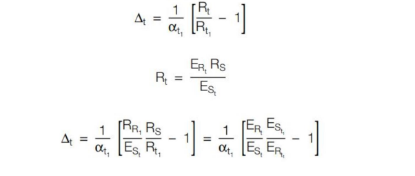
ERt = Voltage drop across test conductor at the desired curꢀrent.
ERt1= Voltage drop across test conductor at the reference current.
ESt = Voltage drop across the external series resistor at the desired current.
ESt1= Voltage drop across the external series resistor at the reference current.
Rs = Resistance of external series resistor.
Rt1 = Resistance of test conductor at the reference temperaꢀture. Determined by measuring voltage drop with less than 100 mA current passing through conductor and determined from