Dielectric Breakdown Voltage and Dielectric Strength
1 Scope These methods are designed for use in determining the dielectric strength of solid electrical insulating materials.
2 Applicable Documents None
3 Test Specimens
3.1 Dimensions The specimens shall be of such a diameter that flashover will not occur. This usually means that the diameter should be 76 mm or more.
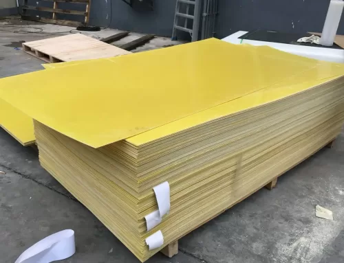
3.2 Thick Solid Materials The breakdown voltage of thick solid materials may be so high that special test specimens cut or molded in reduced thickness may required.
3.3 At Various Thicknesses When it is desired to deterꢀmine the dielectric strength for different thicknesses of a material, it is necessary to test each different
thickness, unless the variation due to thickness is already known.
3.4 Exceptional Conditions The special sizes of specimens required for determining dielectric strength under exceptional conditions shall be as specified in the material specification.
4 Equipment/Apparatus
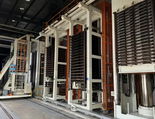
4.1 Transformer The desired test voltage may be most readily obtained by a step-up transformer energized from a variable low-voltage source. The transformer and its controlling equipment shall be of such size and design that the test specimen in circuit, the crest factor (ratio of maximum to mean effective) of the test voltage shall not differ by more than ± 5% from that of a sinusoidal wave over the upper half of the range of test voltage. The crest factor may be checked by means of a sphere gap or peak-reading voltmeter in conjunction with a r.m.s. voltmeter. For test specimens of small capacitance, a testing transformer as small as 500-voltampere rating must be used. Where the wave-form cannot be determined conveniently, a transformer having a rating of not less than 2 kilovolt amperes shall be used for voltages not exceeding 50,000 volts. Tests shall be made at commercial power frequencies. When a transformer is used at voltages lower than its full rating, the current drawn from the high voltage winding should not exceed the full-load full-voltage current rating.
4.2 Circuit Breaker The test transformer circuit shall be protected by an automatic circuit-breaking device designed to open instantaneously on the current produced by breakdown of the test specimen. Excessive flow of current at the time of breakdown causes pitting and heating of the electrodes and thereby increases the work of electrode maintenance and time of testing.
4.3 Voltage Control The rate of voltage rise shall not, for short time tests, vary more than ± 25% from the specified rate. Control of voltage may be secured in one of several ways:
a. Variable-ratio autotransformer
b. Resistance-potential divider
c. Generator-field regulation d. Induction regulator
Preference should be given to equipment having an approximately straight-line voltage-time curve over the desired operating range. Motor drive with variable speed control should be preferred to manual drive because of the difficulty in maintaining reasonable uniform rate of voltage rise with the latter.
4.4 Voltmeter The voltage shall be measured by an approved method, which gives root-mean-square values, preferably by means of
a. A voltmeter connected to the secondary of a separate potential transformer
b. An electrostatic voltmeter in the secondary circuit
c. A voltmeter connected to a well-designed tertiary coil in the test transformer. A voltmeter connected to the primary side of the testing transformer may be used only if
the ratio of transformer does not change appreciably with load.
4.5 Electrodes The electrodes used for thin solid materials (sheets and plates) shall be metal disks 5 mm in diameter and 25 mm in length, with the edges rounded to a radius of 6.4 mm. The electrodes used for thick solid materials shall be metal disks 25 mm in diameter and 25 mm in length, with edges rounded to a radius of 3.2 mm. The electrodes for tapes and sheet materials to be compared with tapes shall be opposing cylindrical rods 6.4 mm in diameter, with edges rounded to a radius of 0.75 mm. The upper movable electrodes shall weigh 45.35g ± 2g. When 6.4 mm electrodes are used, it is advisable that they be surrounded by guard electrodes or shrouds.
4.5.1 The dielectric strength of an insulating material varies with the thickness of the material and the area and geometry of the test electrodes, and these should be specified in the specification. Tests made with different electrodes are not comparable. Where materials are made up into forms of uniꢀform thickness, such as sheets and plates, tests shall be made upon that thickness of material. In other cases, a thickness of the test specimen and diameter and shape of the electrode have been selected,which are compatible with convenience of testing.
4.6 Equipment Testing Apparatus
4.6.1 For Tests Made in Air Use may be made of any well designed oven of sufficient size to hold the test equipment. It should be provided with some means of circulating air so that approximately constant temperature is maintained around the test specimen and with a thermometer or thermocouple for measuring the temperature as near the point of test as practicable to the nearest 1°C.
4.6.2 For Test Under Oil Use may be made of an oil bath, provided with some means for circulating the oil so that the temperature is substantially uniform around the test specimens and with a thermometer or thermocouple for measuring the temperature as near the point of test as practicable to the nearest 1°C.
5 Procedure
5.1 Test Medium The medium to be used in the tests should be specified in the specification. In general, it is preferable to test materials in the medium, whether air or oil, in which they are to be used. Where conditions of use are not well defined, materials should be tested in air up to the point where the breakdown is so high that an excessive amount of material is required to prevent flashover to excessive burning of the surface. For specimens having a high breakdown, such as the thicker and highgrade materials, it is usually necessary to make dielectric strength tests under oil: however; it should be understood that breakdown values obtained under oil are not comparable with those obtained in air.
5.2 Preparing Specimens
5.2.1 In the preparation of test specimens, care shall be taken to have the surfaces adjacent to the electrodes parallel and as plane and smooth as the material permits. The dielectric strength of an insulating material varies with the thickness of the test specimen. Therefore, tests on specimens of different thicknesses are not comparable. The thickness used shall be the average thickness of the sample measured as specified in the specification involved.
5.2.2 The dielectric strength of most insulating materials varies with temperature and humidity. The test coiditions to be used should be specified in the specification. Usually it is desirable to determine the dielectric behavior of a material over the range of temperature and humidity to which it is likely to be subjected in use. When required, materials may be conditioned in a suitably controlled chamber. The test specimen shall be kept in the chamber long enough to reach a uniform temperature and humidity prior to testing. When required, the dielectric strength tests shall be made on the specimen while still in the conditioning chamber. For purpose of tests, a highvoltage conductor may be conveniently carried into the chamber through an insulating bushing.
5.3 Positioning and Care of Electrodes Electrodes shall be held truly coaxial. Where electrodes have flat test faces, the latter shall be parallel to each other. The test faces shall be kept smooth and polished and free from pitting.
5.4 Application of Voltage
5.4.1 Test for Specified Minimum Requirement The voltage shall be applied and increased at a uniform rate from zero to the value specified in the material specification and shall be held at the value for the specified time. Unless otherꢀ wise specified, the rate of rise per second shall be 5% of the specified voltage. Note that this test is to check for ability to withstand a specified voltage and not to determine the breakdown value.
5.4.2 Test to Breakdown, Short-time Test The voltage shall be increased from zero to breakdown at a uniform rate. The rate of rise shall be 0.5 or 1.0 kilovolts per second. depending on the total test time required and the voltage-time characteristic of the material. The rate of rise of voltage should be specified in the material specification.
5.4.3 Test to Breakdown, Step-by-Step Test An initial voltage shall be applied equal to 50 of the breakdown voltage in the short-time test, adjusted as shown in Table 1.
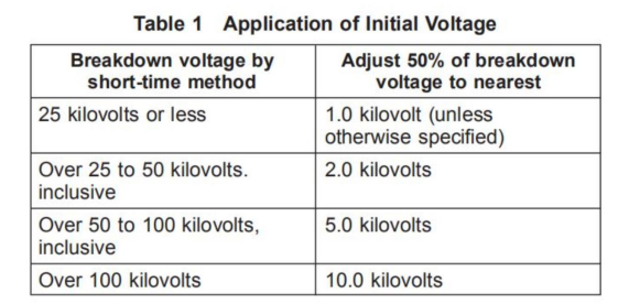
The voltage shall then be increased in equal increments as stated in the various material specifications, the voltage being held at each step for a definite time as stated in the specifications. The change from each step to the next higher shall be made as rapidly as possible and the time of change included in the succeeding test interval.
5.4.4 Test to Breakdown, Slow-Rate-of-Test An initial voltage shall be applied equal to approximately 50% of the breakdown voltage in the short time test, unless otherwise specified. The voltage shall then be increased at a uniform rate up to the point of breakdown. Unless otherwise specified, the rate should be chosen to give approximately the same voltage-time exposure of the test specimen, as provided in the step-by-step test.
5.4.5 Determining Rate of Rise of Voltage The rate of voltage rise may be calculated from measurements of time required to raise the voltage between two prescribed values. When motordriven regulating equipment is used, the speedꢀ control rheostat may be calibrated in terms of voltage rise for any particular test transformer.
5.5 Number of Tests Unless otherwise specified, five tests shall be made. If the average deviation from the mean exceeds 10% or if any individual test deviates more than 15% from the mean, five additional tests shall be made.
5.6 Report
The report shall include the following data:
1. The average thickness of the sample 2. Breakdown voltage at each puncture
3. Volts per mil for each puncture
4. The average, maximum, and minimum volts per 0.0075 mm for each sample
5. The temperature of the surrounding medium should be recorded
6. The RH% of the surrounding air
7. The conditioning treatment 8. The duration of the test
9. In the step-by-step test, the value of the initially applied voltage and the voltage increment
10. In the slow rate of rise test, the value of the initially applied voltage and the rate of rise of the voltage
11. The size and type of electrodes
12. The test medium (air or type of oil)
6 Notes
Due to the high voltage used in this test method, extreme caution should be exercised.