Porosity Testing of Gold Electrodeposited on a Nic
Substrate Electrographic Method
1 Scope
This test method provides a procedure for testing the porosity of gold electroplated from an alkaline (cyanide), acid, or neutral gold plating solution on a nickel substrate in contact with the gold deposit.
2 Applicable Documents :None
3 Materials and Equipment
3.1 Materials :Acetone, Sodium Nitrate, Reagent GD. (NaNO3), Sodium Carbonate, Anhydrous, Reagent GD. (Na2CO3), Dimethylglyoxime, Denatured Ethyl Alcohol No. 3A, Reagent GD. (C2H5OH), hotographic Paper with Silver Halide removed. (Kodabromide, glossy finish, single wt. phoꢀtographic paper (fixed before use), Ammonium Hydroxide, Reagent GD. (NH4OH)
3.2 Equipment
3.2.1 DC power supply to 0 amp to 1 amp. DC minimum, 0 volts to 10 volts
3.2.2 DC Milliammeter, 0 mA to 100 mA
3.2.3 Electrographic Clamp-Press
4 Equipment/Apparatus :None
5 Procedure
5.1 Solution Make Up
5.1.1 Electrolyte :Concentration: NaNO3 1% (wt.) Na2CO3, Anhydr. 4% (wt.) Distilled water – balance by wt. Preparation of 500 g (Vol. of 485 ± 10 ml.) of solution
5.1.1.1 Obtain the tare weight of 600-ml glass beaker.
5.1.1.2 Add 400 ml of distilled water to beaker.
5.1.1.3 Using agitation and, if necessary, heating to 48.9°C, dissolve the following in the water: Sodium nitrate–5g Sodium carbonate – 20 g
5.1.1.4 After salts are dissolved, add distilled water until the net weight of the solution is 500 g.
5.1.1.5 Cool the solution to room temperature before use. 5.2 Indicator Solution The solution is a concentration of dimethylglyoxime – 1% (wt.) denatured ethyl alcohol No. 3A – Balance. Perform the preparation of 300 g (vol. of 380 ± 10 ml.) of solution as explained in
5.2.1 through
5.2.1 Obtain the tare weight of 400-ml glass beaker.
5.2.2 Add 275 ml denatured ethyl alcohol to the beaker.
5.2.3 Using agitation only (do not heat), dissolve 3 g of dimꢀethylglyoxime in the alcohol.
5.2.4 After all additions are dissolved, add denatured ethyl alcohol until the net weight of the solution is 300 g.
5.3 Electrographic Test
5.3.1 Cleaning Procedure
5.3.1.1 Using a cloth, wash the contact area with alconox solution.
5.3.1.2 Rinse the contact area in tap water.
5.3.1.3 Rinse the contact area in deionized water.
5.3.1.4 Rinse the contact area with acetone and air dry.
5.4 Cut a piece of silver halide-free photographic paper to a size slightly larger than the area of the sample or part of the sample being tested. The dimensions of the photographic paper should not exceed the dimension of that part of the sample being porosity tested by more than 0.79375 mm in any one direction.
5.5 Wet the photographic paper, cut in 5.2 with the electroꢀlyte solution prepared in 5.1.1. The photographic paper is immersed for 30 minutes or more in the electrolyte. The Institute for Interconnecting and Packaging Electronic Circuits 2215 Sanders Road • Northbrook, IL 60062-6135
I
After saturating the photographic paper with electrolyte, press the paper between two paper towels to ensure any excess electrolyte is removed from the photographic paper.
5.6 Assemble the sample being tested for porosity and the photographic paper of 5.5 in the electrographic clamp-press as explained in 5.6.1 through 5.6.6.
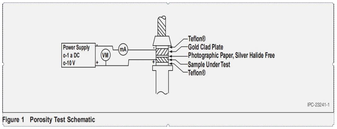
5.6.1 Place a piece of Teflon or equivalent insulating mateꢀrial on the platform of the compression spring and piston device on the clamp-press.
5.6.2 Place the back of the sample or area of sample being tested on top of and in contact with the Teflon.
5.6.3 Place the silver halide-free photographic paper satuꢀrated with electrolyte in 5.5 on top of and in contact with the face of the sample or area of the sample being tested. The emulsion side of the paper should be in contact with the test sample.
5.6.4 Place a piece of pure gold or gold-clad copper on top of the photographic paper so the gold surface is in contact with the photographic paper. The gold or gold-clad material placed on the photographic paper is to have the same maximum dimensions as that part of the sample being porosity tested. The minimum dimensions of the gold or gold-clad material is to be not more than 0.79375 mm shorter than the dimensions of the area being tested in any one direction. Attach a lead wire to the gold or gold-clad material in order to make electrical contact.
5.6.5 Place a piece of Teflon or equivalent insulating mateꢀrial on the back of the gold or gold-clad material.
5.6.6 Lower the screw of the clamping and screw the device until the pressure end of the screw is just in contact with the back of the Teflon and holds the assembly in place. Do not apply force at this time. See 5.11 for a schematic diaꢀgram of assembly.
5.7 Compress the spring of the clamp-press by tightening the screw device until a pressure is exerted on the assembly as in 5.6.6.
5.8 Connect a DC power source so the positive (+) voltage contacts the sample being tested and the negative (-) voltage is connected to the lead of the gold or gold-clad material of 5.6.6. Apply a current, such that the current density is 250 mA ± 50 mA per square inch of surface in contact with the phoꢀtographic paper. Applied voltage should not exceed 10 volts. If the current density of 250 ± 50 mA/sq. in. cannot be obtained at ≤10 volts, then the time of current flow should be increased while holding the potential at 10 volts. The increased time of current flow
can be calculated by the followꢀing formula. Time of current flow (sec) = 250 mA/sq. in. of surface in contact with paper Current density in mA/sq. in. at 10 volts x 60 sec The time of the current flow should be 60 ± 1 sec.
5.9 Unclamp the assembly and remove the silver halide-free photographic paper.
5.10 Apply one to two drops of the indiicator solution from 5.2. to the photographic paper.
5.11 Develop the photographic paper containing indicator solution by holding the paper over an ammonium hydroxide solution.
5.12 Dry the photographic paper to which indicator solution was added and read the test results.
5.13 Observe the porosity test schematic, as shown in Figꢀure 1.
5.14 Test Results
5.15 Nickel exposure through the gold will show up on the indicating photographic paper as a red stain. Copper expoꢀsure will show up as green stains. This exposure is caused by pores, cracking, or unplated areas. These stains should be examined under 10X min, 15X max. 5.15.1 Pores Pores will show up as fine dots.
5.15.2 Cracking Cracks will show up as continuous fine lines.
5.15.3 Unplated Areas Unplated areas will show up as large blots or red lines.