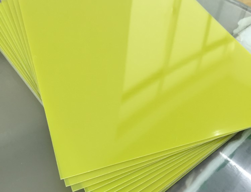
FR4 epoxy board processing method

There are many other names, including FR-4 light sheet, FR-4 fiber sheet, FR-4 epoxy sheet, FR-4 flame retardant sheet, so many names also reflect the wide application of FR-4 fiberglass sheet from other side. . FR-4 fiberglass sheet is generally used for soft-packing base layer, and then wrapped with fabric, leather, etc., to make beautiful wall and ceiling decoration. The application is very extensive. With sound absorption, sound insulation, heat insulation, environmental protection, flame retardant and so on. The following is a detailed analysis of the performance characteristics of FR-4 glass fiberglass sheet: FR-4 epoxy fiberglass cloth, which is a kind of substrate with epoxy resin as binder and electronic grade glass fiber cloth as reinforcing material. Its bonding sheet and inner core thin copper clad plate are important substrates for making multilayer printed circuit boards.
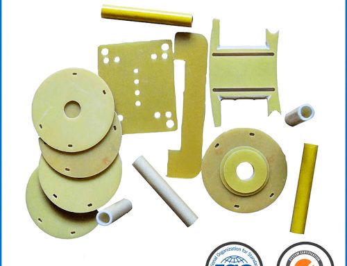
Performance: The mechanical properties, dimensional stability, impact resistance and moisture resistance of the epoxy fiberglass substrate are higher than those of the paper substrate. Its electrical performance is excellent, its operating temperature is high, and its performance is less affected by the environment. In terms of processing technology, it has great advantages over other resin fiberglass cloth substrates. These products are mainly used for double-sided PCBs and are used in large quantities. Stable electrical insulation performance, good flatness, smooth surface, no pits, thickness tolerance standards, suitable for high performance electronic insulation requirements, such as FPC reinforcement board, PCB drilling pad, glass fiber meson, potentiometer carbon Film printing fiberglass board, precision star gear (wafer grinding), precision test board, gas (electrical) equipment insulation struts, insulation pads, transformer insulation board, motor insulation parts, grinding gears, electronic switch insulation boards, etc.
Surface preparation and treatment of FR-4 epoxy glass cloth laminate
- After the copper surface is patterned and etched to form a circuit, try to reduce the handling and contact of the PTFE surface. The operator should wear clean gloves and place a film on each board for transfer to the next procedure.
- The etched PTFE surface has sufficient roughness for bonding. Where the lamella is etched or where the laminate is not covered, it is recommended that the PTFE surface be treated to provide adequate attachment. The chemical components used in the pth preparation process can also be used for surface treatment. Plasma etching or sodium containing chemicals are recommended.
- Copper surface treatment should ensure optimum bond strength. The brown copper oxide circuit treatment will reinforce the surface shape for chemical bonding using TacBond adhesive. The first process requires a cleaner to remove residual and processing oil. A fine copper etch is then performed to form a uniform rough surface area. The brown oxide needle crystals stabilize the adhesive layer during lamination. As with any chemical process, adequate cleaning after each step is required. Salt residue will inhibit adhesion. The final rinse should be supervised and maintained at a pH of less than 8.5. Dry layer by layer and ensure that the surface is not contaminated by oil on your hands.
Overlay and lamination
Recommended bonding (press or plate) temperature: 425 ° F (220 ° C)
- Bake the plate at 250oF (100 ° C) to remove moisture. The plies are stored in a tightly controlled environment and used within 24 hours.
- A pressure field should be used between the tool plate and the first plate to distribute the pressure in the control panel evenly. The high voltage regions present in the board and in the board to be filled will be absorbed by the field. The field also unifies the temperature from the outside to the center. Thereby forming a uniform thickness between the control board and the control board.
- The board must consist of a thin layer of TAC BOND supplied by the supplier. Be careful to prevent contamination when cutting thin layers and stacking. Depending on the circuit design and filling requirements, 1 to 3 bonded layers are required. The areas that need to be filled and the dielectric requirements are used to calculate the 0.0015″ (38 micron) sheet. It is recommended to use clean steel or aluminum mirror plates between the laminates.
- To assist in lamination, vacuum treatment is carried out for 20 minutes before heating. The vacuum is maintained throughout the cycle. Pumping away from the air will help ensure that the circuit is packaged.
- Place a thermocouple in the peripheral area of the center plate to determine temperature monitoring and appropriate cycles.
- The plate can be loaded onto a cold or preheated press platen. If the pressure field is not used for compensation, the heat rise and cycle will be different. It is not critical to enter heat into the package, but it should be controlled to minimize the gap between the perimeter and the center. Typically, the heat rate is between 12-20oF/min (6-9 °C/min) and 425oF (220 °C).
- Once loaded into the press, the pressure can be applied immediately. The pressure will also vary with the size of the control board. It should be controlled within the range of 100-200 psi (7-14 bar).
- Maintain hot pressing at 425oF (230°C) for at least 15 minutes. The temperature must not exceed 450oF (235°C).
- During the lamination process, minimize the time of no pressure (such as the time from the hot press to the cold press). Maintain pressure in the pressure state until it is below 200oF (100°C).